Delta V Block Diagram
Https Www Emerson Com Documents Automation Product Data Sheet Deltav Control Network Hardware En 57648 Pdf

Kerbal Space Program Print Friendly Delta V Map With Images
Https Www Emerson Com Documents Automation Product Data Sheet Deltav Electronic Marshalling Distributed Charms En 4762954 Pdf

Ksp Delta V Map For Real Solar System Lights Out Version With
Digital Communication Delta Modulation Tutorialspoint

Delta V Map With Images Kerbal Space Program Space Program

Step sequencer lsseq drives a number of discrete block outputs based on the input sequence number.
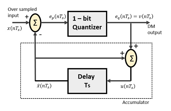
Delta v block diagram. Basics of delta modulation 3. Wiring and installation guidelines edition 1 5 1 chapter 1 power installation guidelines this chapter describes the power wiring practices for all delta controls class 2 24 v ac products. Delta sigma modulation is inspired by delta modulation as shown in figure 2 if quantization were homogeneous e g if it were linear the following would be a sufficient derivation of the equivalence. State transition diagram lsstd implements a state machine.
The two antennas have been placed further apart and have more robust sma sockets furthermore the device has an improved dynamic range and a better frequency response uniform to 6 5 ghz. The relay output terminal block is used for high current ac outputs such as motor starters needing up to 5 amps per channel. 0 00 page 4 of 8 may 1995 figure 9. Start with a block diagram of a delta modulator demodulator.
In this video i have explained adaptive delta modulation by following outlines. Hi7190 2nd order sigma delta modulator figure 10. Analog input lsai reads a single analog signal from an analog input channel and makes it available to other function. 1 working principles of plc ladder diagram 1 4 dvp plc application manual reverse current of traditional ladder diagram x6 x0 x1 x2 x3 a x4 x5 b y0 there is a fault in the 3rd row of ladder diagram.
Working of delta modulation 5. This document does not describe line voltage wiring practices. Hi7190 spectral plot referring back to the block diagram of figure 1 it is seen that dac 0 input. A brief introduction to sigma delta conversion an9504 rev.
But what if i use a 4 wire i o terminal block. Basics of adaptive delta modulation 3. Delta v ecm is an improved version of delta v and is housed in a slightly larger enclosure. Block diagram of adaptive delta modulation 4.
The 2 wire transmitter is just an additional to the card. Blocks are compatible with all charm types. Follow these guidelines to ensure optimum performance of your delta controls products. The block changes state based on the values of its transition inputs.
Block diagram of delta modulation 4. In this video i have explained delta modulation by following outlines. Btw the reason is that i have 4 wire transmitters connected to the other channels of the ai card and i don t want to replace the already existing 4 wire i o terminal block. The linearity property of integration makes it possible to move the integrator which reconstructs the.

1 0 4 Wac S Delta V Map Continued Opm Now Included July 4th
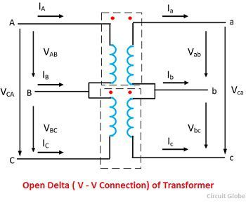
Three Phase Transformer Connections Circuit Globe

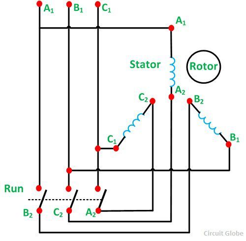
Forward Reverse 3 Phase Ac Motor Control Star Delta Wiring Diagram

Electrical Connection Diagrams Jj Loughran

Ksp Delta V Chart Google Search With Images Kerbal Space

Star Delta Starter Control Wiring Electrical Circuit Diagram

15 Subway Style Maps That Explain Everything But Subways Solar

Fundamental Principles Behind The Sigma Delta Adc Topology Part 2
What Is Star Delta Starter Its Theory Circuit Globe

Three Phase Motor Connection Star Delta Y D Reverse Forward
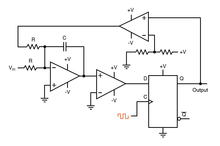
Delta Sigma Adc Digital Analog Conversion Electronics Textbook

Delta Table Saw Wiring Diagram Delta Table Saw Sears Table Saw

A Delta V Map Of The Kerbin System From Kerbal Space Program
